How to Interface with Atari Driving Controller – Arduino Programming
The Atari driving controller uses a 16 position encoder that sends pulses to to pin 1 and pin 2 of the game port. These pulses can be deciphered or decoded to understand if the player is spinning the controller in the left or right direction.
Here is how the spinners encoder works. If you look at the photo below, imagine point A is connected to Pin 1 and Point B is connector to Pin 2. As you spin the encoder the will make contact with the C blocks which are connected to common ground. So at the position shown, pin 1 (A) and Pin 2 (B) are not touching ground (C). but is you spin right, Pin 1 (A) will touch ground first but if you spin left, Pin 2 (B) will Touch ground first.
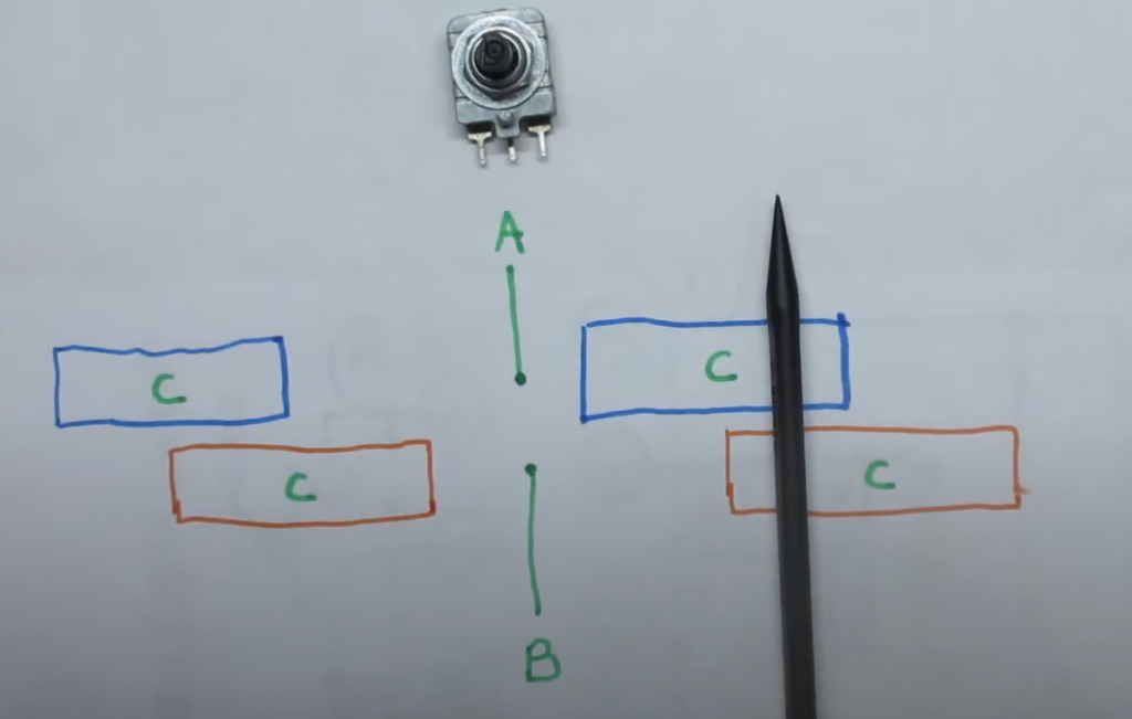
So if you are in the middle where A and B are not touching ground. you go from BA being 00 to 01, and if you spin a bit more you get to where the black pen is where the value becomes 11. Then if you keep going, you go to 10 and then back to 00.
Now if you spin left, you go from being 00 to 10, then 11, then 01.
All the programmer has to do is read the state of pin 1 and pin 2 continuously and compare it to its previous values to determine the direction the play turned. Here is a table that tells you if the player turned right or left based on the current and prior readings of pins 1 and 2.
With only 2 pins there are 4 possible combinations of values that Pin 1 and 2 can produce, like a 2 bit binary number.
| Pin 2 | Pin 1 | 2 bit Value |
| 0 | 0 | 0 |
| 0 | 1 | 1 |
| 1 | 0 | 2 |
| 1 | 1 | 3 |
| Previous Value | Current Value | Direction |
| 0 | 1 | Right |
| 1 | 3 | Right |
| 2 | 0 | Right |
| 3 | 2 | Right |
| 0 | 2 | Left |
| 1 | 0 | Left |
| 2 | 3 | Left |
| 3 | 1 | Left |
Now we have all the logic we need to develop the pseudocode
- Get state of pins 1 and 2
- For current value, combine the pin values like binary bits and convert to decimal
- compare the current value to old value
- if the value has changed from perivious value,
- Use table above to determine if you will move left or right
- update the previous value to current value
- go back to step 1.
So all we need to do is connect pin 1 and 2 to pulled up IO ports of a micro controller. For the fire button, use pin 6 and connect it to a pulled up IO port. When the player presses fire button, pin 6 will go low. When the player spins, you can figure out easily if they spined right or left now!
Here is some sample code assuming you have used GPIO ports 1 for Pin 1, 2 for pin 2 and 3 for pin 6 (fire):
bool A;
bool B;
bool F;
int P=0;

void setup() {
    pinMode(1, INPUT_PULLUP);
    pinMode(2, INPUT_PULLUP);
    pinMode(3, INPUT_PULLUP);
}

void loop() {
    A = !digitalRead(1);
    B = !digitalRead(2);
    F = !digitalRead(3);

    int V = A+B*2;
    if (V != P) {
       if ((P==0 && V==1) || (P==1 && V==3) || (P==2 && V==0) || (P==3 && V==2)) {
           // Moved right code goes here
       } else if ((P==0 && V==2) || (P==1 && V==0) || (P==2 && V==3) || (P==3 && V==1)) {
           // Moved left code goes here
       }
       P = V;
    }
}
document.getElementById in asp.net with Master Pages
Using JavaScript to locate controls in ASP.net pages that are linked to master pages can be tricky. This is because the ASP.net reassigns control IDs dynamically and the names change.
A simple solution is to use asp.net inline Tags.
For Example:
Instead for using:
document.getElementById(“Label1″)
try using:
document.getElementById(“<%=Label1.ClientID%>”)
C# function for a Bezier Curve
The Bezier Curve formula below can be used to define smooth curves between points in space using line handlers (line P0 to P1 and line P2 to P3).
P(t) = (1-t)^3P0 + 3(1-t)^2tP1 + 3(1-t)t^2P2 + t^3P3
At t=0 you will be at p0, and at t=1 you will be at p3.
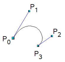
The function below is a C# implementation of the formula return the X and Y coordinates of a position on the curve for a given Time (t) and the 4 points that define the Bezier Curve.
You can easily extend this to connect multiple curves to each other (multi-segmented path). You can do this simply by making p0 of subsequent segments equal p3 of the prior segment.
Include this function in your c# projects to create smooth curves.
C# Code Sample:
private Vector2 GetPoint(float t, Vector2 p0, Vector2 p1, Vector2 p2, Vector2 p3)
{
  float cx = 3 * (p1.X - p0.X);
  float cy = 3 * (p1.Y - p0.Y);
  float bx = 3 * (p2.X - p1.X) - cx;
  float by = 3 * (p2.Y - p1.Y) - cy;
  float ax = p3.X - p0.X - cx - bx;
  float ay = p3.Y - p0.Y - cy - by;
  float Cube = t * t * t;
  float Square = t * t;

  float resX = (ax * Cube) + (bx * Square) + (cx * t) + p0.X;
  float resY = (ay * Cube) + (by * Square) + (cy * t) + p0.Y;

  return new Vector2(resX, resY);
}
To use the function, simply pass in the 4 point and a time (between 0 and 1). To draw the curve, try calling this function from a for loop that looks something like this:
// preset your p0,p1,p2,p3

Vector2 PlotPoint;
for (float t = 0;  t <= 1.0f; t += 0.01f)
{
   PlotPoint = GetPoint(t, p0, p1, p2, p3);

   // now call some function to plot the PlotPoint
   YourDrawFunction(PlotPoint);
}
This basically starts you at p0 when time t is zero and at each increment of time +0.01 you will slowly move on the curve towards p3.
So to give you an idea of how this was used by my son in one of his games, watch the video below
- Note these are circular Paths each withe 3 segments. Each segment is a 4 point Bezier calculation.
- p3 of the each segment is common to p0 of next each segment.
- To make the circular, p3 of last segment must be same as p0 of 1st segment.
- p2 and p3 of each segment must be on a strait line with p0 and p1 or the next segment. (this give you the double handles for each point)
So this means:
- If a path point was moved by user, you must also move left and right control handler points by same deltas
- If left handler moved, must also move corresponding path point so it intersects line to other handler at mid point
- If right handler moved, must also move corresponding path point so it intersects line to other handler at mid point
Good luck
