Atari Dual Paddles as Independent Gamepads? Here’s How the iCode Ultimate Adapter Has the Answer.
If you’ve ever tried to get two-player Atari paddle games working on modern hardware, you know the frustration. Maybe it’s MiSTer FPGA where Player 2 is completely invisible. Maybe it’s RetroArch where you spent an hour buried in input configuration menus trying to map the Y axis to a second virtual player. Maybe it’s a standalone emulator that simply doesn’t support two paddles on one gamepad at all.
Your paddles are fine. Your adapter is fine. The problem is how USB adapters have traditionally reported paddle data — and it creates headaches on virtually every platform. Some emulators can work around it with enough manual configuration. Most can’t. And even when they can, the process is error-prone, poorly documented, and different for every emulator. Until now, nobody has solved this at the adapter level where it belongs.
The Problem: Two Paddles, One Gamepad
Atari paddles come in pairs. A single DE-9 connector carries two paddles — each with its own potentiometer and fire button — sharing the same port. The original 2600 handled this natively because it was designed around this exact hardware. Paddle A and Paddle B were simply two separate inputs on the same controller port.
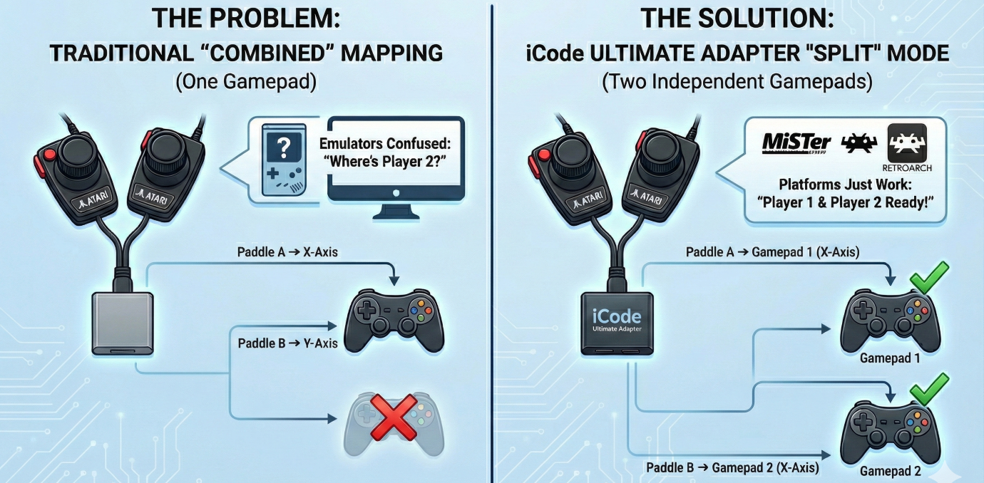
When USB adapters came along, they had to translate this into something a modern computer could understand. The standard approach became: map Paddle A to the X axis of a gamepad, Paddle B to the Y axis, and the two fire buttons to buttons 0 and 1. One physical port, one USB gamepad, two axes. Simple, clean, and it works — for emulators that know how to read it.
Even emulators that theoretically support this — like RetroArch or Stella — aren’t straightforward. You might get lucky after spending hours digging through input configuration menus, remapping axes, and praying it sticks between sessions. And then you update the emulator or switch cores and get to do it all over again. The reality is that no platform handles the “two paddles on one gamepad” approach gracefully.
Why Most Platforms Struggle with Dual Paddles
The root of the problem is simple: most platforms expect one gamepad per player.
MiSTer FPGA’s Atari cores expect Player 1 on gamepad 1’s X axis and Player 2 on gamepad 2’s X axis. It never looks at the Y axis for a second paddle — it looks for a second USB device entirely. Player 2 is completely invisible.
But MiSTer is just the most obvious example. The same issue appears everywhere:
- RetroArch can technically handle it, but you have to manually configure input remapping to bind the Y axis of gamepad 1 to Player 2’s paddle input. The process is buried in nested menus, varies by core, and resets if you change controllers. Most users never get it working.
- RetroPie inherits RetroArch’s complexity and adds its own layer of input configuration on top. Getting dual paddles working often means editing config files by hand.
- Standalone emulators like Atari800 or MAME each have their own input mapping systems, each with different assumptions about how paddles should arrive over USB. What works in one breaks in another.
- FPGA platforms beyond MiSTer — including Analogue devices and other retro FPGA projects — generally follow the one-gamepad-per-player model.
The common thread is that every platform requires you to solve the same problem from the receiving end, with platform-specific configuration that’s fragile, frustrating, and easy to get wrong. Change your adapter, update your emulator, or switch platforms, and you’re starting over.
The real fix belongs at the source — in the adapter itself.
Our Solution: Split Mode
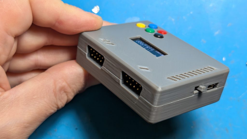
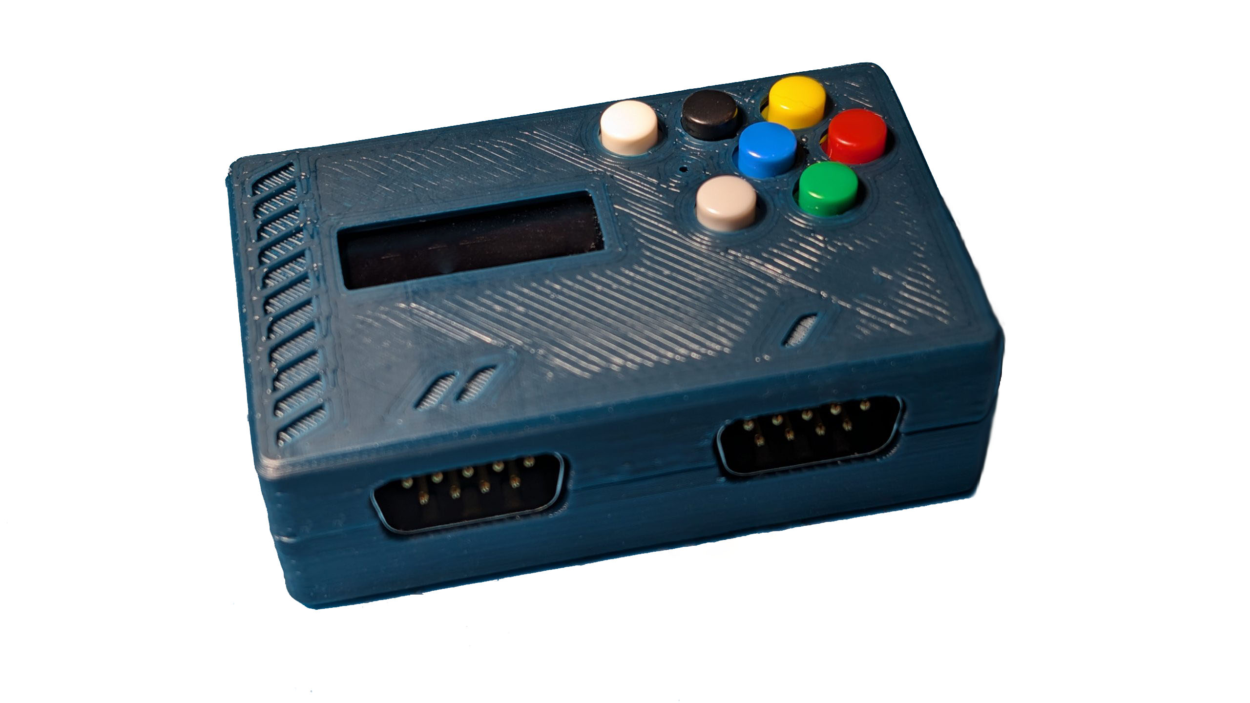
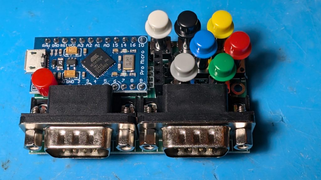
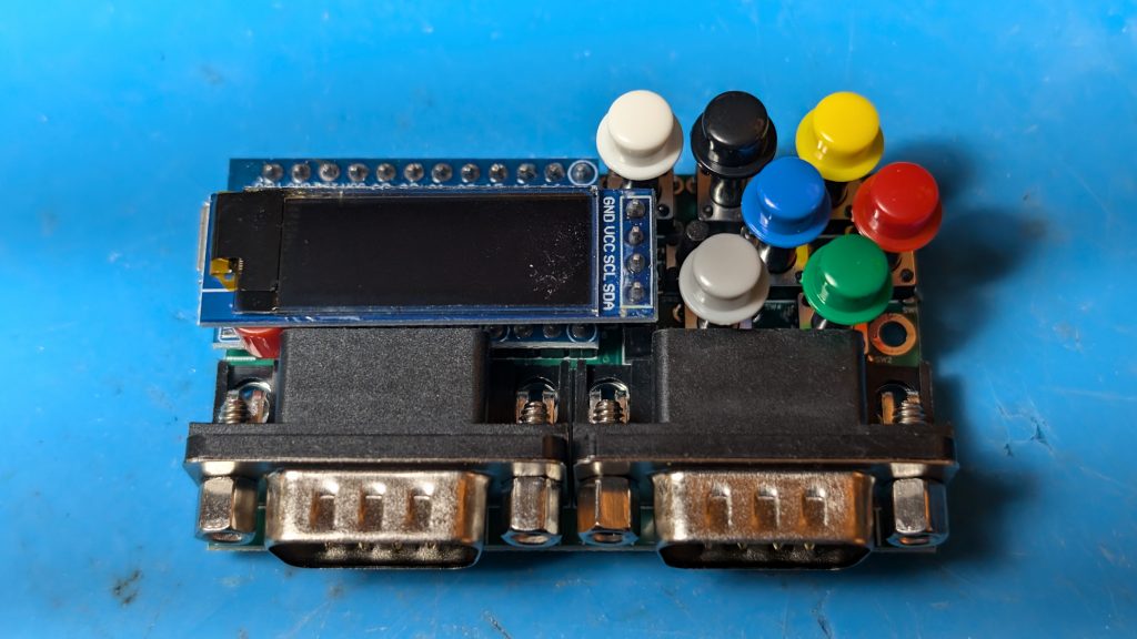
The iCode Duo Ultimate Adapter now includes a Dual Paddles setting with two modes: Combined and Split.
Combined is the traditional behavior. Both paddles from a port map to the same USB gamepad — Paddle A on X, Paddle B on Y, fire buttons on buttons 0 and 1. This is the default and may work on some emulators with manual input configuration — if you have the patience.
Split solves the compatibility problem at the source. When activated, the adapter remaps the paddle data across both USB gamepads:
| Physical Source | → | USB Output | Player |
|---|---|---|---|
| Port 0 Paddle A | → | Gamepad 1, X axis + Btn 0 | Player 1 |
| Port 0 Paddle B | → | Gamepad 2, X axis + Btn 0 | Player 2 |
Every platform — MiSTer, RetroArch, RetroPie, MAME, standalone emulators, FPGA devices — now sees exactly what it expects: two independent controllers, each with a paddle on the X axis. Player 1 and Player 2 just work. No input remapping, no config file editing, no per-emulator workarounds. Flip one setting on the adapter and you’re done.
What About Four Paddles?
This is where it gets interesting. If you have paddles connected to both ports — the full four-paddle setup for games like Warlords — Split mode handles that too.
| Physical Source | → | USB Output | Player |
|---|---|---|---|
| Port 0 Paddle A | → | Gamepad 1, X axis + Btn 0 | Player 1 |
| Port 1 Paddle A | → | Gamepad 1, Y axis + Btn 1 | Player 3 |
| Port 0 Paddle B | → | Gamepad 2, X axis + Btn 0 | Player 2 |
| Port 1 Paddle B | → | Gamepad 2, Y axis + Btn 1 | Player 4 |
Gamepad 1 carries both “A” paddles, Gamepad 2 carries both “B” paddles. Platforms that expect one paddle per gamepad pick up Players 1 and 2 from the X axes automatically, and emulators that support four paddles can read all four from the two gamepads.
The adapter intelligently manages this — Split mode only activates when both ports actually have paddles available. If you’ve got a joystick on Port 1 and paddles on Port 0, the adapter stays in Combined mode regardless of the setting. No conflicts, no confusion.
Settings Follow the Destination
One design decision we’re particularly happy with is how settings work in Split mode. Each USB gamepad’s paddle behavior — resolution, jitter control, button mapping — is controlled by the port settings for that gamepad’s slot. Gamepad 1 uses Port 1’s settings, Gamepad 2 uses Port 2’s settings.
This means you can configure each player’s paddle experience independently through the menu, and the settings make intuitive sense: what you configure under “Port 1” always controls what comes out of USB Gamepad 1, regardless of which physical paddle is being mapped there.
Stick + Paddles Still Works
For Stick+Paddles mode, Split works seamlessly alongside digital joystick input. The joystick from Port 0 routes to Gamepad 1, and the joystick from Port 1 routes to Gamepad 2 — exactly where you’d expect them. The paddle split only affects the analog data and fire buttons, so your digital controls remain unchanged.
How to Enable It
1. Navigate to Settings
2. Find Dual Paddles (visible when Console is set to Atari)
3. Select Split
That’s it. No reboot required, no firmware changes, and — most importantly — no configuration needed on the emulator side. No input remapping in RetroArch, no config file editing in RetroPie, no per-core setup on MiSTer. The adapter sends the data the right way from the start, so every platform just works.
The Bigger Picture
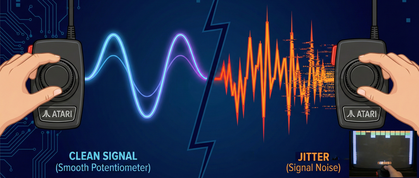
This is part of our ongoing effort to make the iCode Duo Ultimate Adapter work everywhere, not just in the most common setups. Paddle support has always been a pain point for the retro gaming community — between jitter issues, calibration problems, and now platform compatibility — and we’ve been systematically knocking down every barrier.
Combined with our four-stage jitter elimination pipeline, auto-calibration, and adjustable resolution control, Split mode means Atari paddles finally work the way they should on every platform. Whether you’re playing Breakout on RetroArch or Warlords on MiSTer, the iCode Ultimate Adapter handles it — and your paddles just feel right.