Extracting Transparency from Flattened Images
Ever had a semi-transparent graphic — a glass effect, a soft shadow, a wisp of smoke — that got flattened onto a solid background? The transparency data is gone. Or is it?
With a surprisingly elegant trick, you can perfectly recover the original transparency by comparing the same image on two different backgrounds. Here’s how.
Quick Start: How to Do It
The whole process is two steps:
1 Prepare two versions of your image. Upload your image to Google Gemini Pro and ask:
Convert this image to a pure solid white #FFFFFF background and keep everything else exactly unchanged
Save the result as white.png. Then, using the white image you just created, ask:
Change the white background to a solid pure black #000000. Keep everything else exactly unchanged
Save the result as black.png.
(It’s important to create black from the white version rather than generating both independently — this ensures the foreground stays perfectly aligned between the two images.)
2 Run the extraction tool. Build the executable (instructions below) and run:
.\extract-alpha.exe white.png black.png output.pngThat’s it. output.png is your image with the background removed and full transparency recovered — including semi-transparent edges, shadows, and glass effects that normal background removal tools destroy.
How It Works
The Problem
Let’s say you have a layer in Photoshop, After Effects, or a game engine with semi-transparent pixels. At some point it gets composited onto a solid background and exported as a flat image — a JPEG, a screenshot, a video frame. The alpha channel is gone.
You can’t just threshold or magic-wand your way back, because semi-transparent pixels have blended with the background. A 50% transparent white pixel on a black background looks like medium gray. On a white background, it just looks white. The information about what was foreground and what was transparency has been mixed together.
But here’s the key insight: it mixed differently depending on the background color. And that difference is exactly what we need.
The Trick: Render It Twice
Take your image and render it on two backgrounds:
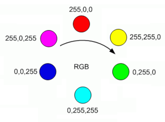
- Once on pure white (255, 255, 255)
- Once on pure black (0, 0, 0)
Now compare each pixel across the two images. The way a pixel changes between the two backgrounds tells you everything about its transparency.
The Math
Think about what happens to a single pixel at different transparency levels.
A fully opaque pixel looks identical on both backgrounds. The background can’t show through, so the color doesn’t change. The distance between the two versions is zero.
A fully transparent pixel takes on the background color completely. On white it appears as (255, 255, 255). On black it appears as (0, 0, 0). The distance between the two versions is the maximum possible — the Euclidean distance between white and black in RGB space:
A semi-transparent pixel falls somewhere in between. The more transparent it is, the more it shifts between backgrounds, and the greater the distance.
This gives us a clean linear relationship:
That’s it. One subtraction and one division per pixel.
Recovering the Original Color
Knowing the alpha isn’t enough — we also need to figure out what color the pixel actually was before it got blended. This is where the black background version comes in handy.
The standard compositing equation for a pixel over a background is:
When the background is black (0, 0, 0), the second term vanishes:
So recovering the true foreground color is just:
We divide each channel by alpha to “un-premultiply” the color — brightening up those semi-transparent pixels that got darkened by the blending process.
A Concrete Example
Imagine a 50% transparent bright red pixel — rgba(255, 0, 0, 0.5):
| Red | Green | Blue | |
|---|---|---|---|
| On white background | 255 | 128 | 128 |
| On black background | 128 | 0 | 0 |
The distance between these two: √((255−128)² + (128−0)² + (128−0)²) ≈ 220.8
Then recover the color from the black version:
R = 128 / 0.5 = 256 → clamped to 255   ✓
G = 0 / 0.5 = 0                         ✓
B = 0 / 0.5 = 0                         ✓
We get back rgba(255, 0, 0, 0.5) — the exact original pixel.
Edge Cases
Near-zero alpha: When alpha is very close to zero, dividing by it amplifies noise. The implementation uses a threshold (alpha > 0.01) and outputs fully transparent black for anything below that.
Clamping: Rounding errors can push values slightly outside the 0–255 range, so everything gets clamped.
Image alignment: The two input images must be exactly the same dimensions and perfectly aligned, pixel for pixel. If you’re capturing screenshots, make sure nothing shifts between the two renders.
Build the Tool
Prerequisites
.NET SDK (8.0 or later)
Setup
# Create the project and add the image library
dotnet new console -n extract-alpha
cd extract-alpha
dotnet add package System.Drawing.Common
Program.cs
Replace the contents of Program.cs with:
using System;
using System.Drawing;
using System.Drawing.Imaging;
using System.Runtime.InteropServices;
using System.Runtime.Versioning;

[SupportedOSPlatform("windows")]
class Program
{
    static void Main(string[] args)
    {
        if (args.Length < 3)
        {
            Console.Error.WriteLine("Usage: extract-alpha.exe <image-on-white> <image-on-black> <output.png>");
            Environment.Exit(1);
        }

        try
        {
            ExtractAlphaTwoPass(args[0], args[1], args[2]);
            Console.WriteLine($"Done! Saved to {args[2]}");
        }
        catch (Exception ex)
        {
            Console.Error.WriteLine($"Error: {ex.Message}");
            Environment.Exit(1);
        }
    }

    static void ExtractAlphaTwoPass(string imgOnWhitePath, string imgOnBlackPath, string outputPath)
    {
        using var imgWhite = new Bitmap(imgOnWhitePath);
        using var imgBlack = new Bitmap(imgOnBlackPath);

        int width = imgWhite.Width;
        int height = imgWhite.Height;

        if (width != imgBlack.Width || height != imgBlack.Height)
            throw new Exception("Dimension mismatch: Images must be identical size");

        using var output = new Bitmap(width, height, PixelFormat.Format32bppArgb);

        // Lock bits for fast pixel access
        var rect = new Rectangle(0, 0, width, height);
        var bdWhite = imgWhite.LockBits(rect, ImageLockMode.ReadOnly, PixelFormat.Format32bppArgb);
        var bdBlack = imgBlack.LockBits(rect, ImageLockMode.ReadOnly, PixelFormat.Format32bppArgb);
        var bdOutput = output.LockBits(rect, ImageLockMode.WriteOnly, PixelFormat.Format32bppArgb);

        int byteCount = width * height * 4;
        byte[] pxWhite = new byte[byteCount];
        byte[] pxBlack = new byte[byteCount];
        byte[] pxOutput = new byte[byteCount];

        Marshal.Copy(bdWhite.Scan0, pxWhite, 0, byteCount);
        Marshal.Copy(bdBlack.Scan0, pxBlack, 0, byteCount);

        // Distance between White and Black: √(255² + 255² + 255²) ≈ 441.67
        double bgDist = Math.Sqrt(3.0 * 255 * 255);

        for (int i = 0; i < width * height; i++)
        {
            int offset = i * 4;

            // Format32bppArgb stores pixels in BGRA order in memory
            byte bW = pxWhite[offset];
            byte gW = pxWhite[offset + 1];
            byte rW = pxWhite[offset + 2];

            byte bB = pxBlack[offset];
            byte gB = pxBlack[offset + 1];
            byte rB = pxBlack[offset + 2];

            // Calculate distance between the two observed pixels
            double pixelDist = Math.Sqrt(
                Math.Pow(rW - rB, 2) +
                Math.Pow(gW - gB, 2) +
                Math.Pow(bW - bB, 2)
            );

            // If 100% opaque: same on both → pixelDist = 0 → alpha = 1
            // If 100% transparent: max difference → pixelDist = bgDist → alpha = 0
            double alpha = 1.0 - (pixelDist / bgDist);
            alpha = Math.Clamp(alpha, 0.0, 1.0);

            // Color Recovery: divide by alpha to un-premultiply
            double rOut = 0, gOut = 0, bOut = 0;

            if (alpha > 0.01)
            {
                rOut = rB / alpha;
                gOut = gB / alpha;
                bOut = bB / alpha;
            }

            // Write in BGRA order
            pxOutput[offset]     = (byte)Math.Min(255, Math.Round(bOut));
            pxOutput[offset + 1] = (byte)Math.Min(255, Math.Round(gOut));
            pxOutput[offset + 2] = (byte)Math.Min(255, Math.Round(rOut));
            pxOutput[offset + 3] = (byte)Math.Min(255, Math.Round(alpha * 255));
        }

        Marshal.Copy(pxOutput, 0, bdOutput.Scan0, byteCount);

        imgWhite.UnlockBits(bdWhite);
        imgBlack.UnlockBits(bdBlack);
        output.UnlockBits(bdOutput);

        output.Save(outputPath, ImageFormat.Png);
    }
}
Build and Run
# Publish as a single self-contained .exe
dotnet publish -c Release -r win-x64 --self-contained true /p:PublishSingleFile=true /p:IncludeNativeLibrariesForSelfExtract=true
The executable will be in bin\Release\net8.0\win-x64\publish\.
.\extract-alpha.exe white.png black.png output.pngA note on System.Drawing
System.Drawing.Common is Windows-only, but since we’re publishing as a Windows exe, that’s fine. The [SupportedOSPlatform("windows")] attribute suppresses the platform warnings. Also note that System.Drawing stores pixels in BGRA order (blue first) in memory, which is why the byte offsets in the code read blue before red.
When Would You Use This?
This technique is useful any time you need to recover transparency from a composited source:
- Game development — extracting UI elements or particles from engine screenshots
- Video compositing — pulling a semi-transparent overlay from rendered frames
- Web scraping — recovering icons or graphics that were served over a solid background
- Legacy asset recovery — reconstructing layered artwork from flattened exports
The only requirement is that you can render the same content on both a white and black background with identical positioning. If you can do that, this technique will recover the alpha channel perfectly — no manual masking, no edge artifacts, no guesswork.