
The Atari driving controller uses a 16 position encoder that sends pulses to to pin 1 and pin 2 of the game port. These pulses can be deciphered or decoded to understand if the player is spinning the controller in the left or right direction.
Here is how the spinners encoder works. If you look at the photo below, imagine point A is connected to Pin 1 and Point B is connector to Pin 2. As you spin the encoder the will make contact with the C blocks which are connected to common ground. So at the position shown, pin 1 (A) and Pin 2 (B) are not touching ground (C). but is you spin right, Pin 1 (A) will touch ground first but if you spin left, Pin 2 (B) will Touch ground first.
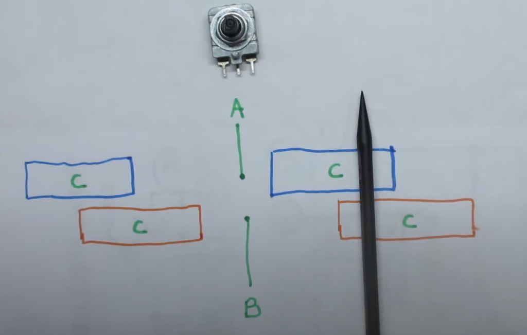
So if you are in the middle where A and B are not touching ground. you go from BA being 00 to 01, and if you spin a bit more you get to where the black pen is where the value becomes 11. Then if you keep going, you go to 10 and then back to 00.
Now if you spin left, you go from being 00 to 10, then 11, then 01.
All the programmer has to do is read the state of pin 1 and pin 2 continuously and compare it to its previous values to determine the direction the play turned. Here is a table that tells you if the player turned right or left based on the current and prior readings of pins 1 and 2.
With only 2 pins there are 4 possible combinations of values that Pin 1 and 2 can produce, like a 2 bit binary number.
| Pin 2 | Pin 1 | 2 bit Value |
| 0 | 0 | 0 |
| 0 | 1 | 1 |
| 1 | 0 | 2 |
| 1 | 1 | 3 |
| Previous Value | Current Value | Direction |
| 0 | 1 | Right |
| 1 | 3 | Right |
| 2 | 0 | Right |
| 3 | 2 | Right |
| 0 | 2 | Left |
| 1 | 0 | Left |
| 2 | 3 | Left |
| 3 | 1 | Left |
Now we have all the logic we need to develop the pseudocode
- Get state of pins 1 and 2
- For current value, combine the pin values like binary bits and convert to decimal
- compare the current value to old value
- if the value has changed from perivious value,
- Use table above to determine if you will move left or right
- update the previous value to current value
- go back to step 1.
So all we need to do is connect pin 1 and 2 to pulled up IO ports of a micro controller. For the fire button, use pin 6 and connect it to a pulled up IO port. When the player presses fire button, pin 6 will go low. When the player spins, you can figure out easily if they spined right or left now!
Here is some sample code assuming you have used GPIO ports 1 for Pin 1, 2 for pin 2 and 3 for pin 6 (fire):
bool A;
bool B;
bool F;
int P=0;

void setup() {
    pinMode(1, INPUT_PULLUP);
    pinMode(2, INPUT_PULLUP);
    pinMode(3, INPUT_PULLUP);
}

void loop() {
    A = !digitalRead(1);
    B = !digitalRead(2);
    F = !digitalRead(3);

    int V = A+B*2;
    if (V != P) {
       if ((P==0 && V==1) || (P==1 && V==3) || (P==2 && V==0) || (P==3 && V==2)) {
           // Moved right code goes here
       } else if ((P==0 && V==2) || (P==1 && V==0) || (P==2 && V==3) || (P==3 && V==1)) {
           // Moved left code goes here
       }
       P = V;
    }
}

Leave a comment
Your email address will not be published. Required fields are marked *